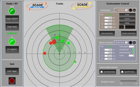
The Sensors Fusion Mission Computer application illustrates, for educational purposes, how tactile interactivity concepts are brought into the fighter cockpit and the air defense control room. The Mission Computer application has been automatically generated from SCADE Suite® and SCADE LifeCycle® Rapid Prototyper.
The main objective of this application is to manage two sensors on-board a military fighter: radar and IFF (Identification Friend or Foe):
- Manage the radar state, the radar scanning mode, the IFF state,
- Merge position, speed, dangerousness data for the surrounding tracks received from both sensors,
- Compute most dangerous tracks,
- Display on the radar the position, speed, nature and priority of the detected tracks,
- Eventually enable the gun to shoot selected track.
In order to simulate the Mission Computer, a simulation environment is provided:
- A radar model: when tracks are within the radar scope, this sensor provides the position and speed vector for detected tracks.
- An IFF model: when tracks are within the IFF scope, this sensor provide the position and kind of the track (FRIEND, FOE, UNKNOWN)
- A simulation control panel (see instructions).
Instructions:
1/ Environment Control
The Environment area allows creation and management of up to 8 tracks around the fighter:
- “Random environment”: randomly generates the position, speed vector, and kind of 8 tracks
- “Clean environment”: suppresses all tracks from the environment
- “Env Track”: displays the position X and Y (in nautical miles), the speed vector SX and SY (in nautical miles per hour) and the Kind of one of the 8 possible track. Selected track is highlighted with a surrounding Orange square in the Tracks area. Clicking on a track in the Tracks area selects it.
- “Delete”: suppresses selected track
- “Random”: replaces selected track by a new “random” one.
- “Define”: allows graphical/tactile definition of a track in the Tracks area: clicking, dragging then releasing the pointer in the Tracks area allows creating the position and speed vector for this new track. Pressing the Set button validates the new position and speed vector.
The Mission Computer area displays consolidated tracks data as computed by the computer:
- “Mission Track”: displays the unique track number, consolidated position X and Y (in nautical miles), the consolidated speed vector SX and SY (in nautical miles per hour) and the Kind of one of the 8 possible tracks. Selected track is highlighted with a surrounding Blue square in the Tracks area.
Clicking on a track in the Tracks area selects it. Priority represents the dangerousness of the track (1 for the most dangerous, 2 for the second, 3 for the third, 0 for all others). This priority level is also shown with circles around the tracks in the Tracks area (3 circles for priority 1, 2 for priority 2, 1 for priority 3, none otherwise)
“Radar Failure” and “IFF Failure” buttons allow injecting a failure in respective sensors.
“Simulation speed” slider allows modifying the simulation speed.
2/ Fighter Sensors and Gun Control
- “Radar ON/OFF”: switch alternatively on and off the radar sensor.
- “Radar Mode”: switch alternatively between the WIDE and NARROW modes of the radar. In WIDE mode, the scope is 10 Knots around the fighter; in NARROW mode, the scope is 25 Knots but reduced to a 40 degrees angle in front of the fighter.
- “IFF ON/OFF”: switch alternatively on and off the IFF sensor. The scope of the IFF is 15 Knots, materialized by a larger green circle on the central part of the application.
- “Lock Target”: toggle enabled only if a dangerous track has been detected by the computer. When pressed, it activates the gun, pointing to the most dangerous track.
- “Gun” (red button): shoot locked target with the gun.

